

MCP4725 is a single channel, 12-bit, voltage output Digital-to-Analog Converter with integrated EEPROM and an I2C Compatible Serial Interface.
mcp4725
Features
12-Bit Resolution
On-Board Non-Volatile Memory (EEPROM)
±0.2 LSB DNL (typ)
External A0 Address Pin
Normal or Power-Down Mode
Fast Settling Time of 6µs (typ)
External Voltage Reference (VDD)
Rail-to-Rail Output
Low Power Consumption
Single-Supply Operation: 2.7V to 5.5V
I2CTM Interface:
Eight Available Addresses
Standard (100 kbps), Fast (400 kbps) andHigh Speed (3.4 Mbps) Modes
Small 6-lead SOT-23 Package
Extended Temperature Range: -40°C to +125°C
As this is a 12 bit DAC converter. What this means is that it will accept up to 4096 possible inputs to provide an analog output, where an output value of zero is zero and an output value of 4095 is full scale.
Full scale is determined by the reference voltage you supply to the VCC pin. Also you can see from above that the supply voltage can be anywhere from 2.7 volts to 5.5 volts. We will use 5v, or as close as what is supplied via the USB in. You may want to measure this voltage for accurate readings, I’ve seen this vary.
This means that to work out the value of the Least Significant Bit (LSB) is as follows:
1 LSB = VCC Voltage / 4096
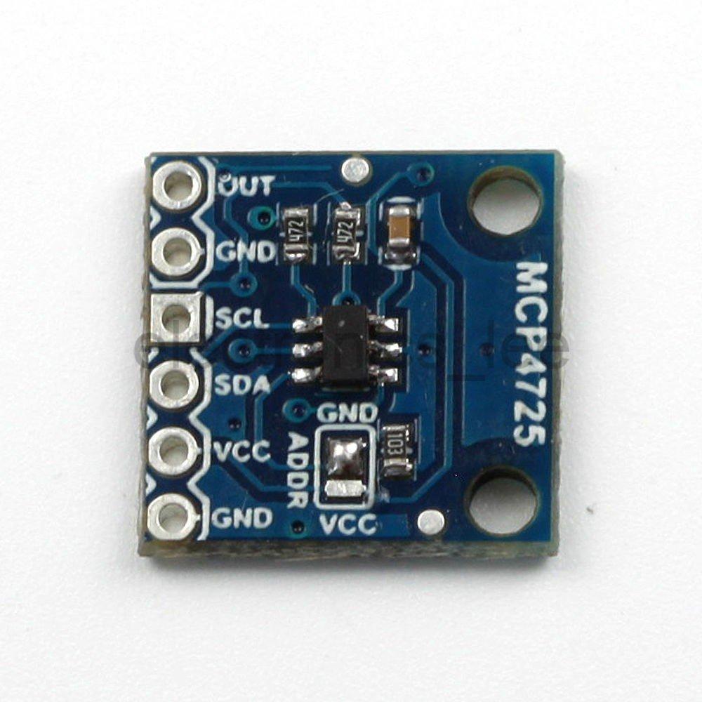
Again the easiest way to interface this to an Arduino is to purchase a module, tehse are available from many sources, here is what my one looked at.
The module has the ability to use different I2C addresses, so run the code from here first. My one was the default 0x60 address
Schematic
This uses an I2C connection and the VOUT/OUT from the module connects to A1 in this example.
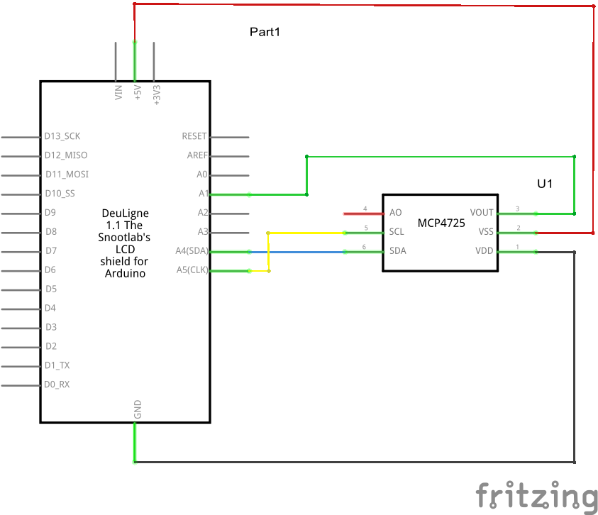
mcp4725 schematic
Code
This code example uses the Adafruit library, in the most recent (1.6.5 onwards) Arduino IDE you can import this using Include Libraries -> Manage Libraries. Basically we increment the DAC, read in the value and display the results on an LCD shield
[codesyntax lang=”cpp”]
#include <Wire.h>
#include <Adafruit_MCP4725.h>
#include <LiquidCrystal.h>


#define MCP4725In A1
Adafruit_MCP4725 MCP4725;
//setup for the LCD keypad shield
LiquidCrystal lcd(8, 9, 4, 5, 6, 7);

void setup()
{
  // put your setup code here, to run once:
  delay(1000);
  lcd.begin(16,2);
  MCP4725.begin(0x60); // The I2C Address of my module
  //line 1 - Expected reading
  lcd.setCursor(0,0);
  lcd.print("Exp: ");
  //line 2 - Actual reading
  lcd.setCursor(0,1);
  lcd.print("Act: ");

}

void loop()
{
  // put your main code here, to run repeatedly:
  uint32_t MCP4725_value;
  int adcInput = 0;
  float voltageIn = 0;
  float MCP4725_reading;
  for (MCP4725_value = 0; MCP4725_value < 4096; MCP4725_value = MCP4725_value + 128)
  {
    delay(1000);
    MCP4725_reading = (5.0/4096.0) * MCP4725_value; //5.0 is your supply voltage
    MCP4725.setVoltage(MCP4725_value, false);
    adcInput = analogRead(MCP4725In); //module output connect to A0
    voltageIn = (adcInput * 5.0 )/ 1024.0;
    lcd.setCursor(7,0);
    lcd.print(MCP4725_reading,3);
    lcd.setCursor(7,1);
    lcd.print(voltageIn,3);
  }

}
[/codesyntax]
Links
MCP4725 I2C DAC Breakout Development Board 12Bit Resolution