

In this article we connect an ADS1115 to a MSP430FR4133 LaunchPad. We will have a basic example using the Energia IDE
The ADS1115 device is a precision, low-power, 16-bit, I2C-compatible, analog-to-digital converters (ADCs) offered in an ultra-small, leadless, X2QFN-10 package, and a VSSOP-10 package. The device incorporates a low-drift voltage reference and an oscillator.
The converter also incorporates a programmable gain amplifier and a digital comparator. These features, along with a wide operating supply range, make the converter well suited for power- and space-constrained, sensor measurement applications.

The ADS1115 perform conversions at data rates up to 860 samples per second (SPS). The PGA offers input ranges from ±256 mV to ±6.144 V, allowing precise large- and small-signal measurements. The converter features an input multiplexer that allows two differential or four single-ended input measurements. Use the digital comparator in the ADS1115 for under- and overvoltage detection.
The ADS1115 operates in either continuous-conversion mode or single-shot mode. The devices are automatically powered down after one conversion in single-shot mode; therefore, power consumption is significantly reduced during idle periods.
ADS1115 Features
Wide Supply Range: 2.0 V to 5.5 V
Low Current Consumption: 150 µA
(Continuous-Conversion Mode)
Programmable Data Rate: 8 SPS to 860 SPS
Single-Cycle Settling
Internal Low-Drift Voltage Reference
Internal Oscillator
I2C Interface: Four Pin-Selectable Addresses
Four Single-Ended or Two Differential Inputs
Programmable Comparator
Operating Temperature Range: –40°C to +125°C
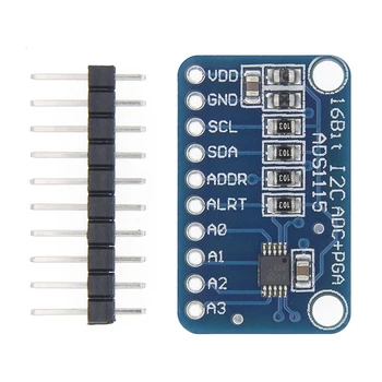
This is the module I bought
Parts Required
| Name | Link |
| MSP430FR4133 LaunchPad | MSP430FR4133 LaunchPad development board MSP-EXP430FR4133 |
| ADS1115 module | 16 Bit I2C ADS1115 Module ADC 4 channel with Pro Gain Amplifier RPi |
| Connecting wire | Free shipping Dupont line 120pcs 20cm male to male + male to female and female to female jumper wire |
Schematic/Connection
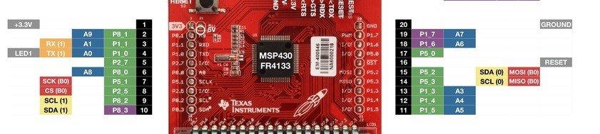
Here are the connectors on the launchpad
| MSP430FR4133 Launchpad | Sensor |
| 3.3v | Vdd |
| Gnd | Gnd |
| SDA P8_2 | SDA |
| SCL P8_3 | SCL |
Code Example
[codesyntax lang=”cpp”]
#include <Wire.h>

// ADS1115 I2C address is 0x48(72)
#define Addr 0x48

void setup()
{
  // Initialise I2C communication as MASTER
  Wire.begin();
  // Initialise Serial Communication, set baud rate = 9600
  Serial.begin(9600);

  // Start I2C Transmission
  Wire.beginTransmission(Addr);
  // Select configuration register
  Wire.write(0x01);
  // AINP = AIN0 and AINN = AIN1, +/- 2.048V
  Wire.write(0x84);
  // Continuous conversion mode, 128 SPS
  Wire.write(0x83);
  // Stop I2C Transmission
  Wire.endTransmission();
  delay(300);
}

void loop()
{
  unsigned int data[2];

  // Start I2C Transmission
  Wire.beginTransmission(Addr);
  // Select data register
  Wire.write(0x00);
  // Stop I2C Transmission
  Wire.endTransmission();

  // Request 2 bytes of data
  Wire.requestFrom(Addr, 2);

  // Read 2 bytes of data
  // raw_adc msb, raw_adc lsb
  if (Wire.available() == 2)
  {
    data[0] = Wire.read();
    data[1] = Wire.read();
  }

  // Convert the data
  int raw_adc = (data[0] * 256) + data[1];
  if (raw_adc > 32767)
  {
    raw_adc -= 65535;
  }

  // Output data to serial monitor
  Serial.print("Digital Value of Analog Input : ");
  Serial.println(raw_adc);
  delay(500);
}
[/codesyntax]
Output
Open the serial monitor and you should see something like this
Digital Value of Analog Input : 527
Digital Value of Analog Input : 538
Digital Value of Analog Input : 484
Digital Value of Analog Input : 5
Digital Value of Analog Input : 6
Digital Value of Analog Input : 2
Digital Value of Analog Input : 1
Digital Value of Analog Input : 29
Links
http://www.ti.com/lit/ds/symlink/ads1115.pdf
I2C ADS1115 16 Bit ADC 4 channel Module with Programmable Gain Amplifier 2.0V to 5.5V RPi