

In this example we will show you how to connect a 7 segment display to our PIC18F2550. You can think of a 7 segment display as 7 individual LEDs in a configuration like the picture below.
Image 1 shows the layout and image 2 shows how the segments are arranged
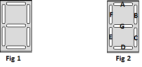
7 seg Blank
So by lighting certain segments you can display numbers, so for example to display the number 1 you would light segments B and C. Here are more examples
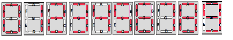
7 segment
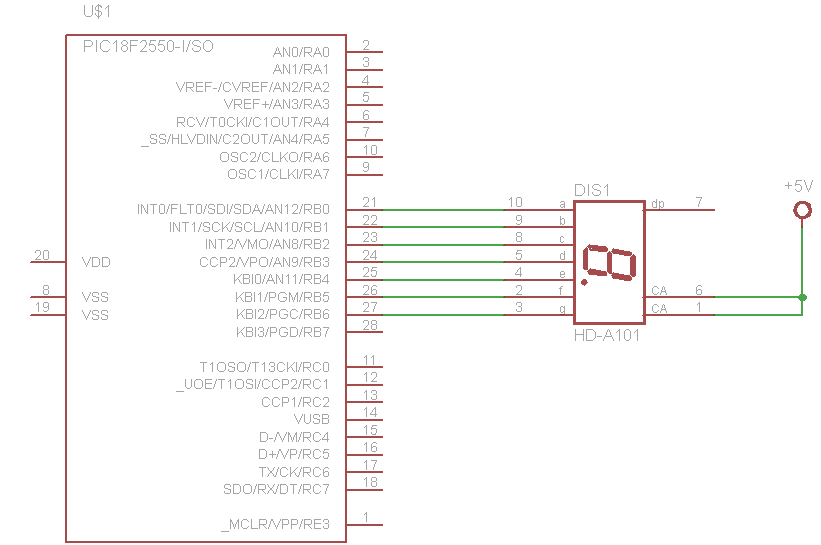
In this example we connect a HDSP-C3Y3 common anode display to our PIC18F2550, you can see the connections in the schematic below. We basically connect up segment A to PD0, segment B to PD1 and so on.
Schematic
I didn’t connect the DP but you can easily connect it to PORT B pin 7 and adapt the code if you desired
pic18f2550 and seven segment
Code
The code was written in mikroC pro for PIC
<pre>int main(void)
{
TRISB = 0x00; // Configure port D as output
while(1)
{


PORTB = 0xC0; // Display Number 0
delay_ms(3000); // Wait for 1s
PORTB = 0xF9; // Display Number 1
delay_ms(3000); // Wait for 1s
PORTB = 0xA4; // Display Number 2
delay_ms(3000); // Wait for 1s
PORTB = 0xB0; // Display Number 3
delay_ms(3000); // Wait for 1s
PORTB = 0x99; // Display Letter 4
delay_ms(3000); // Wait for 1s
PORTB = 0x92; // Display Letter 5
delay_ms(3000); // Wait for 1s
PORTB = 0x82; // Display Letter 6
delay_ms(3000); // Wait for 1s
PORTB = 0xF8; // Display Letter 7
delay_ms(3000); // Wait for 1s
PORTB = 0x80; // Display Letter 8
delay_ms(3000); // Wait for 1s
PORTB = 0x90; // Display Letter 9
delay_ms(3000); // Wait for 1s
}
}
</pre>
Links
20 PCS LD-3161BG 1 Digit 0.36″ GREEN 7 SEGMENT LED DISPLAY COMMON ANODE