

3.1K
In this part we will now try and program an Attiny85 microcontroller using an Arduino, the process is similar to our Attiny2313 example. Basically slightly different connections and change the chip being programmed in the IDE.
Connections
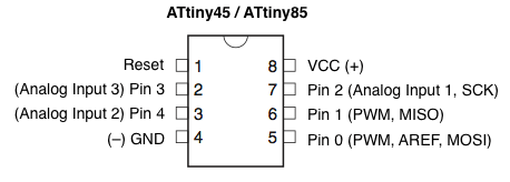
ATtiny85
- ATtiny Pin 7 to Arduino Pin 13 (SCK)
- ATtiny Pin 6 to Arduino Pin 12 (MISO)
- ATtiny Pin 5 to Arduino Pin 11 (MOSI)
- ATtiny Pin 1 to Arduino Pin 10 (RESET)
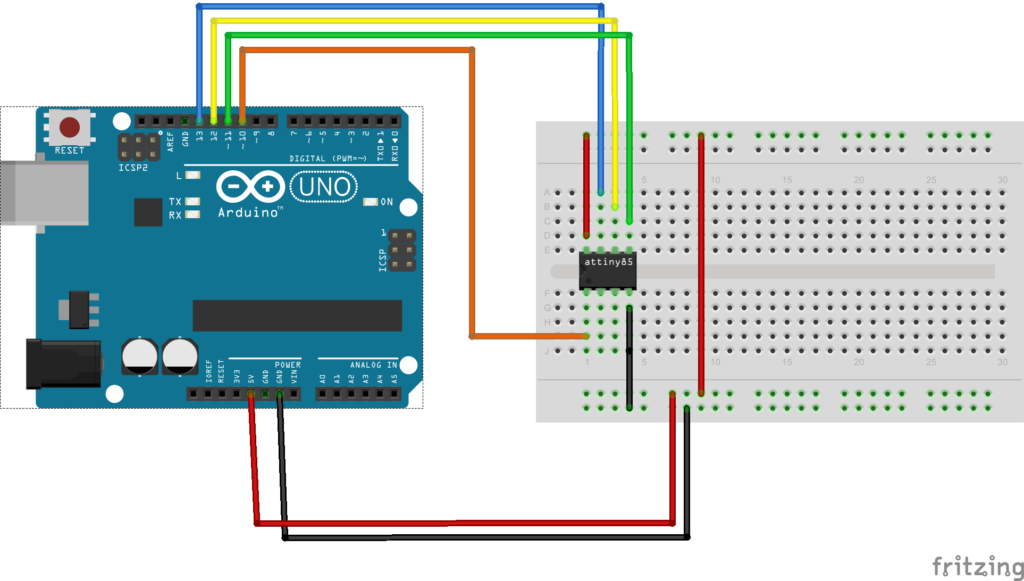
Layout

Arduino to atttiny85
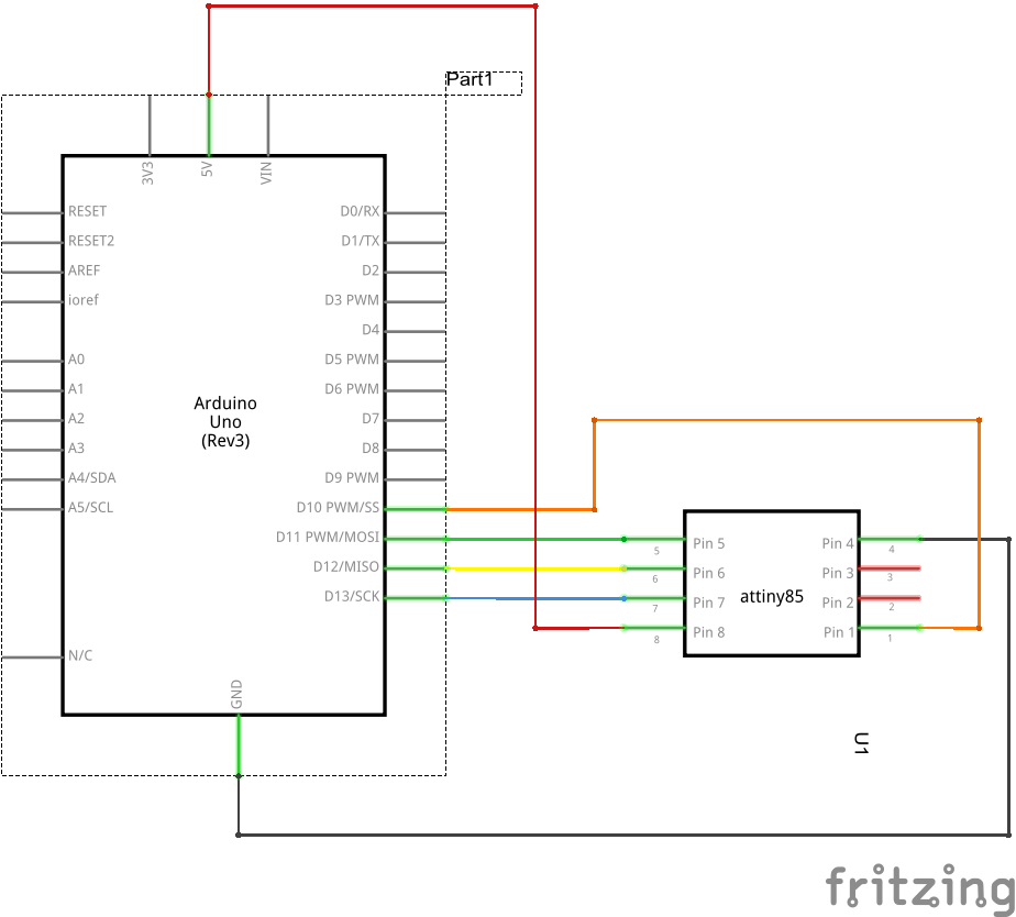
Schematic
Arduino to atttiny85 schematic
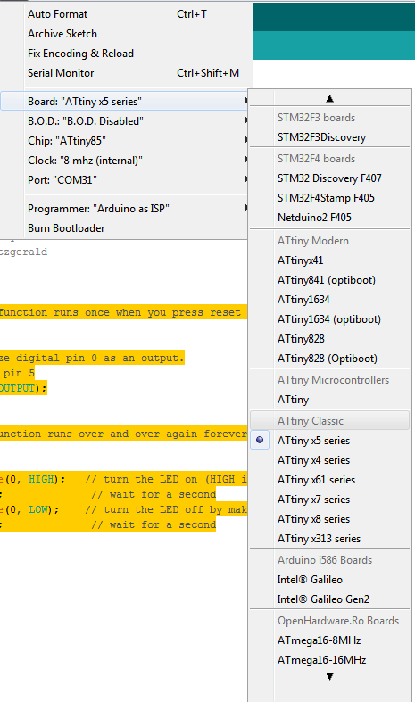
You will need to setup your Arduino, here is a screenshot of my settings
attiny85 setup
Code
Modify the basic blink LED sketch to use Pin 5 (D0)
[codesyntax lang=”cpp”]
// the setup function runs once when you press reset or power the board
void setup()
{
  // initialize digital pin 0 as an output.
  // Attint85 pin 5
  pinMode(0, OUTPUT);
}

// the loop function runs over and over again forever
void loop()
{
  digitalWrite(0, HIGH);   // turn the LED on (HIGH is the voltage level)
  delay(1000);              // wait for a second
  digitalWrite(0, LOW);    // turn the LED off by making the voltage LOW
  delay(1000);              // wait for a second
}
[/codesyntax]