

In this example we connect an ADS1115 analog-to-digital converters to a Raspberry Pi. Lets look at the ADS1115.
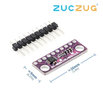
The ADS1115 is a precision, low-power, 16-bit, I2C-compatible, analog-to-digital converters (ADCs) offered in an ultra-small, leadless, X2QFN-10 package, and a VSSOP-10 package. The ADS1115 incorporates a low-drift voltage reference and an oscillator.
The ADS1115 also incorporate a programmable gain amplifier (PGA) and a digital comparator. These features, along with a wide operating supply range, make the ADS1115 well suited for power- and space-constrained, sensor measurement applications.
The ADS1115 performs conversions at data rates up to 860 samples per second (SPS). The PGA offers input ranges from ±256 mV to ±6.144 V, allowing precise large- and small-signal measurements. The ADS1115 features an input multiplexer (MUX) that allows two differential or four single-ended input measurements. Use the digital comparator in the ADS1115 for under- and overvoltage detection.
The ADS1115 operates in either continuous-conversion mode or single-shot mode. The devices are automatically powered down after one conversion in single-shot mode; therefore, power consumption is significantly reduced during idle periods.
Connection
In this example I had connected the sensor to a Pi Zero, a Raspberry Pi 2 or 3 would work just as well. I also used a cable which I would use to connect and disconnect to Channel 0 to check the readings changed.
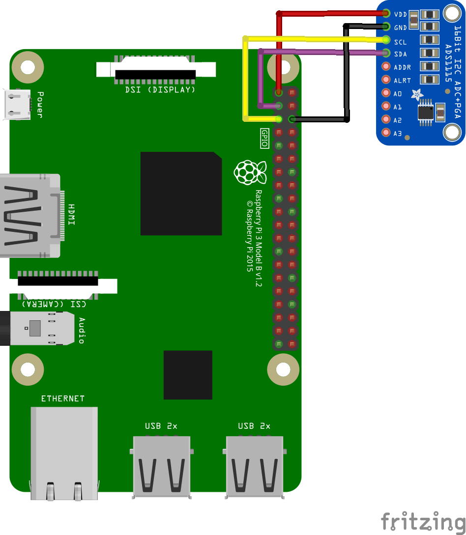
pi and ads1115 layout
Parts List
| Part | Link |
| Raspberry PI 4 | Latest Raspberry Pi 4 Model B with 1/2/4GB RAM |
| ADS1115 breakout | ADS1115 16 Bit ADC 4 channel Module with Programmable Gain Amplifier 2.0V to 5.5V |
| Connecting cables | Free shipping Dupont line 120pcs 20cm male to male + male to female and female to female jumper wire |
Code
This is an example from https://github.com/ControlEverythingCommunity/ADS1115
Save the following as ADS1115.c
[codesyntax lang=”cpp”]
import com.pi4j.io.i2c.I2CBus;
import com.pi4j.io.i2c.I2CDevice;
import com.pi4j.io.i2c.I2CFactory;
import java.io.IOException;

public class ADS1115
{
	public static void main(String args[]) throws Exception
	{
		// Create I2C bus
		I2CBus bus = I2CFactory.getInstance(I2CBus.BUS_1);
		// Get I2C device, ADS1115 I2C address is 0x48(72)
		I2CDevice device = bus.getDevice(0x48);

		byte[] config = {(byte)0x84, (byte)0x83};
		// Select configuration register
		// AINP = AIN0 and AINN = AIN1, +/- 2.048V, Continuous conversion mode, 128 SPS
		device.write(0x01, config, 0, 2);
		Thread.sleep(500);

		// Read 2 bytes of data
		// raw_adc msb, raw_adc lsb
		byte[] data = new byte[2];
		device.read(0x00, data, 0, 2);

		// Convert the data
		int raw_adc = ((data[0] & 0xFF) * 256) + (data[1] & 0xFF);
		if (raw_adc > 32767)
		{
			raw_adc -= 65535;
		}

		// Output data to screen
		System.out.printf("Digital Value of Analog Input : %d %n", raw_adc);
	}
}
[/codesyntax]
Output
Run the above example by opening a terminal and typing in
gcc ADS1115.c -o ADS1115
In the example you input the channel number, in the output below you can see I have 2 values displayed. This is when I connected a Gnd to Channel 0 – thats the low value and then disconnected this – the high value
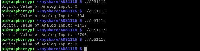
pi and ads1115 output