

In this article we will have a look at the Digispark, we will also have some articles about using the board with various sensors and modules
Development
The Digispark supports all features found in the IDE with the exception of the serial monitor and the burn bootloader functionality.
Many existing libraries will not work with the Digispark: For I2C devices check out the TinyWireM library, which makes it super simple to port an I2C based device library over to use with the Digispark.
Pin functions:
-
All pins can be used as Digital I/O
-
Pin 0 → I2C SDA, PWM (LED on Model B)
-
Pin 1 → PWM (LED on Model A)
-
Pin 2 → I2C SCK, Analog In
-
Pin 3 → Analog In (also used for USB+ when USB is in use)
-
Pin 4 → PWM, Analog (also used for USB- when USB is in use)
-
Pin 5 → Analog In
Frequently Asked questions
-
GPIO output is 20 mA max per pin, same as a regular Arduino.
-
I2C pins are Pin 0 (I2C data/SDA) and Pin 2 (I2C clock/SCL).
-
USB communication uses pins #3 and #4. Using these pins for your circuit can interfere with the USB interface, e.g. reprogramming the Digispark. So it’s a good idea to provide some sort of disconnect ability if you use either of these two pins.
-
PWM output available on Pins 0, 1, 4.
-
LED is on P1 for all Digispark labeled Rev2 or higher., P0 for those with no Rev label.
-
All Rev3 Digisparks are counterfeit! (we never made a rev3)
-
VIN pin takes 7-12v (6-32 may work but over 12 will probably need some heat sinking) and can output 500ma (but over 100-200 might need some heat sinking)
-
5V pin takes 4.5-5.5v (3v+ may work, but not supported)
-
USB connector takes 5v (4.5-6v may work but not supported)
-
Pin 3 has a 1.5K pull-up (for USB communications)
-
Pin 5 has some limitations it cannot handle as much current is outputs more like 3.6v – but works fine for most non-current sourcing uses
Using the Digispark with the Arduino IDE:
The Digispark works a bit differently than some Arduino compatible products. The Digispark programs with a different procedure.
From the Tools menu select Board→Digispark (Default – 16.5Mhz)
(The Tools→Programmer selection does not matter)
Write some code, open your code, or open a Digispark example.
You do not need to plug in your Digispark before invoking upload
Hit the upload button. The bottom status box will now ask you to plug in your Digispark – at this point you need to plug it in – or unplug and replug it.
You’ll see the upload progress and then it will immediately run your code on the Digispark.
If you unplug the Digispark and plug it back in or attach it to another power source there will be a delay of 5 seconds before the code you programmed will run. This 5 second delay is the Digispark Pro checking to see if you are trying to program it.
This is what I saw in the output window
Running Digispark Uploader...
Plug in device now... (will timeout in 60 seconds)
> Please plug in the device ...
> Press CTRL+C to terminate the program.
> Device is found!
connecting: 16% complete
connecting: 22% complete
Pinout
Here is a pinout for the basic Digispark basic
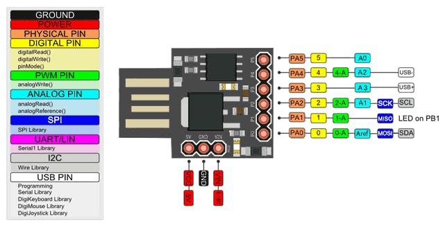
digispark-pinout
Schematic
This is a sample schematic
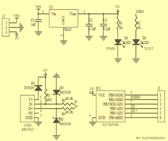
ATtiny85 schematic
Links
http://digistump.com/wiki/digispark/tutorials/connecting