

In this simple example for a Digispark board we connect an RGB LED to it. We will then use the Arduino IDE to write a sketch and upload it to the board.
I used an OLIMEXINO-85 but a basic Digispark will work as well
Schematic
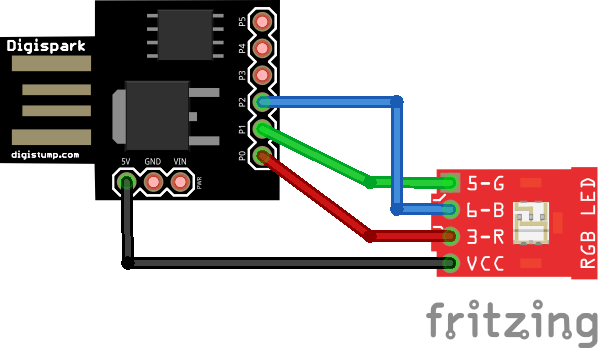
digispark rgb led
Parts
I use an RGB led module as you can see in the schematic above, you can quite easily just purchase an RGB led and the required resistors, this was just easier to connect. You can see the module below

| £2.19 from Aliexpress | |
| £0.84 from Aliexpress | |
Examples
Here are some examples, these are all designed for a common anode type RGB led,.
If you had a common cathode type you would have to change the low to high and vice versa in the code
[codesyntax lang=”cpp”]
void setup() {
    // Initialize the LED pins as outputs
    pinMode(0, OUTPUT);
    pinMode(1, OUTPUT);
    pinMode(2, OUTPUT);
}

void loop() {
    digitalWrite(0, LOW);  // Turn the red LED On
    delay(500);            // Wait for a second
    digitalWrite(0, HIGH);   // Turn the red LED off
    delay(500);            // Wait for a second
    digitalWrite(1, LOW);  // Turn the green LED On
    delay(500);            // Wait for a second
    digitalWrite(1, HIGH);   // Turn the green LED off
    delay(500);            // Wait for a second
    digitalWrite(2, LOW);  // Turn the blue LED On
    delay(500);            // Wait for a second
    digitalWrite(2, HIGH);  // Turn the blue LED off
    delay(500);            // Wait for a second
}
[/codesyntax]
And this example uses analogwrite
[codesyntax lang=”cpp”]
int r = 0;
int g = 1;
int b = 2;

void setup() {
 pinMode(r,OUTPUT);
 pinMode(g,OUTPUT);
 pinMode(b,OUTPUT);
}


void loop() {
  analogWrite(r,0);
  analogWrite(g,255);
  analogWrite(b,255);
  delay(1000);
  analogWrite(r,255);
  analogWrite(g,0);
  analogWrite(b,255);
  delay(1000);
  analogWrite(r,255);
  analogWrite(g,255);
  analogWrite(b,0);
  delay(1000);
}
[/codesyntax]
And this uses the Digispark RGB library
[codesyntax lang=”cpp”]
#include <DigisparkRGB.h>
/*
 Digispark RGB

 This example shows how to use soft PWM to fade 3 colors.
 Note: This is only necessary for PB2 (pin 2) - Blue, as Red (pin 0) and Green (pin 1) as well as pin 4 support the standard Arduino analogWrite() function.

 This example code is in the public domain.
 */
byte RED = 0;
byte BLUE = 2;
byte GREEN = 1;
byte COLORS[] = {RED, BLUE, GREEN};

// the setup routine runs once when you press reset:
void setup()  {
  DigisparkRGBBegin();
}


void loop ()
{
//direction: up = true, down = false
boolean dir = true;
int i = 0;

while(1)
{
fade(COLORS[i%3], dir);
i++;
dir = !dir;
}
}
void fade(byte Led, boolean dir)
{
int i;

//if fading up
if (dir)
{
for (i = 0; i < 256; i++)
{
DigisparkRGB(Led, i);
DigisparkRGBDelay(25);//1);
}
}
else
{
for (i = 255; i >= 0; i--)
{
DigisparkRGB(Led, i);
DigisparkRGBDelay(25);//1);
}
}
}
[/codesyntax]