

In this example we connect an RGB led module to a 8051F340 development board, we will have a simple example which cycles through the red, green and blue colors
The LED we used was a common anode type. if you have a common cathode type then you will have to invert the values in the code later on.
Remember for one of the led’s to light for a common anode type we need to make the cathode go low. This is the module that I used
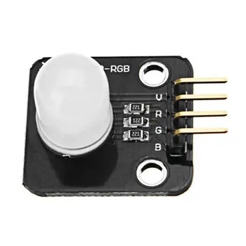 Full Color Led Module 10Mm High Brightness Rgb Full Color Led
Parts
We used the generic 8051F340 development board
The RGB led was a little module that contained the resistors required as well, rather than messing with breadboards and components that can be easier
| Name | Link |
| C8051F340 Development Board | C8051F340 Development Board |
| C8051F MCU emulator | C8051F MCU emulator downloader U-EC6 EC6 Enterprise Edition |
| RGB LED | Full Color Led Module 10Mm High Brightness Rgb Full Color Led |
| Connecting wire | male to male + male to female and female to female DuPont cable |
Schematic
Basically red cathode to P2.0, green cathode to p2.1 and blue cathode to P2.2 for my module.
This was something I quickly knocked up in Eagle to show this

Code
This code example uses a fairly crude delay function to put it mildly, we will be looking at different ways of doing this and also looking at different compilers in later articles. Some of these have built in delay functions.
This was adapted from the F34x_PortIO example using the Silabs IDE
//-----------------------------------------------------------------------------
// Includes
//-----------------------------------------------------------------------------

#include <SI_C8051F340_Register_Enums.h>

//-----------------------------------------------------------------------------
// Pin Declarations
//-----------------------------------------------------------------------------
SI_SBIT(RED, SFR_P2, 0);                  // SW1 ='0' means switch pressed
SI_SBIT(GREEN, SFR_P2, 1);                  // SW2 ='0' means switch pressed
SI_SBIT(BLUE, SFR_P2, 2);                      // LED='1' means ON


//-----------------------------------------------------------------------------
// Function Prototypes
//-----------------------------------------------------------------------------

void OSCILLATOR_Init (void);
void PORT_Init (void);

//-----------------------------------------------------------------------------
// SiLabs_Startup() Routine
// ----------------------------------------------------------------------------
// This function is called immediately after reset, before the initialization
// code is run in SILABS_STARTUP.A51 (which runs before main() ). This is a
// useful place to disable the watchdog timer, which is enable by default
// and may trigger before main() in some instances.
//-----------------------------------------------------------------------------
void SiLabs_Startup (void)
{
   PCA0MD &= ~0x40;                    // WDTE = 0 (clear watchdog timer
}

//very primitive delay function
void delay(unsigned int t)
{
   unsigned int i,j;
   for(i=0;i<t;i++)
       for(j=0;j<250;j++);
}

//-----------------------------------------------------------------------------
// main() Routine
//-----------------------------------------------------------------------------

void main (void)
{
                                       // enable)

   PORT_Init();                        // Initialize Port I/O
   OSCILLATOR_Init ();                 // Initialize Oscillator

   while (1)
   {
    	 RED = 0;                     // Turn on LED
    	 GREEN = 1;
    	 BLUE = 1;
    	 delay(1000);
    	 RED = 1;                     // Turn on LED
    	 GREEN = 1;
    	 BLUE = 1;
    	 delay(1000);

    	 RED = 1;                     // Turn on LED
    	 GREEN = 0;
    	 BLUE = 1;
    	 delay(1000);
    	 RED = 1;                     // Turn on LED
    	 GREEN = 1;
    	 BLUE = 1;
    	 delay(1000);

    	 RED = 1;                     // Turn on LED
    	 GREEN = 1;
    	 BLUE = 0;
    	 delay(1000);
    	 RED = 1;                     // Turn on LED
    	 GREEN = 1;
    	 BLUE = 1;
    	 delay(1000);
   }                                   // end of while(1)
}                                      // end of main()

//-----------------------------------------------------------------------------
// Initialization Subroutines
//-----------------------------------------------------------------------------

//-----------------------------------------------------------------------------
// OSCILLATOR_Init
//-----------------------------------------------------------------------------
// This function initializes the system clock to use the internal oscillator
// at its maximum frequency.
//
//-----------------------------------------------------------------------------
void OSCILLATOR_Init (void)
{
   OSCICN |= 0x03;                     // Configure internal oscillator for
                                       // its maximum frequency (24.5 Mhz)
}


void PORT_Init (void)
{
   P2MDIN |= 0x0F;                     // Lower four pins on P2 are digital
   P2MDOUT = 0x0F;                     // enable LEDs as push-pull outputs
   P2     |= 0x0F;                     // Set port latches for P2.0, 1,2,3
   XBR1    = 0x40;                     // Enable crossbar and enable weak pull-ups
}